 README
README
G3N-Mesh-Tutorial
This is a basic tutorial which shows you how to create a mesh in G3N from scratch using only a .png texture.
This tutorial was built on how I learned LWJGL3 from this tutorial: https://lwjglgamedev.gitbooks.io/3d-game-development-with-lwjgl/content/
If you see any ways to improve this tutorial, please let me know.
If you are brand new to Go I recommend: Tech With Tim Golang Tutorial
I'm going to assume you're using VSCODE, Code, or CODE OSS, and your IDE's terminal is already in the directory of the program in this tutorial.
Let's get started.
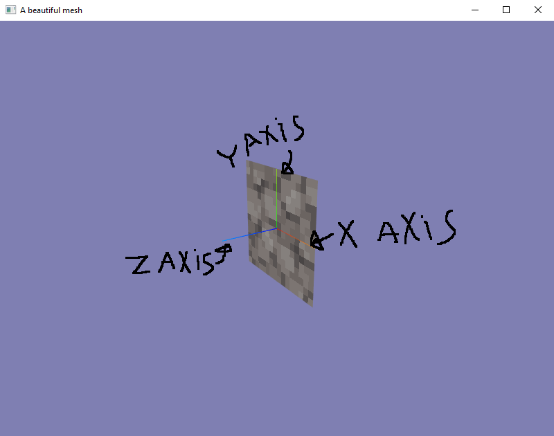
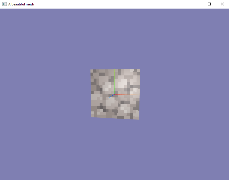
First of all, this is how this tutorial looks when you run:
$ go build && ./G3N-Mesh-Tutorial
On Linux or
$ go build; .\G3N-Mesh-Tutorial.exe
On Windows.
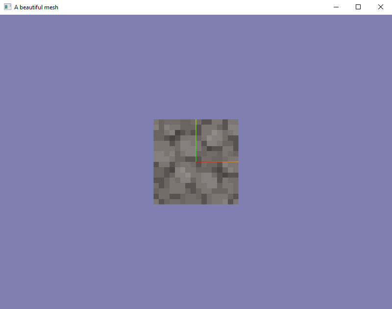
As you can see, this is extremely basic. But every program starts off extremely basic. It only matters where your imagination can and will take you with it.
Question: Okay what am I looking at? Isn't this from the game Crafting Mine or something?
Answer: No, this is a simple .png image used as a texture material, created from 2 tris with a helper coordinate axis in G3N labeled "A beautiful mesh".
Okay maybe that is a bit complex to unload to someone new to this, let me make it a little bit simpler.
Verbatem from Google: A mesh is a collection of vertices, edges and faces that define the shape of a 3D object.
Sadly they left off the part where a mesh usually has a material plopped on it, but we'll get to that.
Step 1, Vertex Positions:
Let's start off with the simplest thing in that definition, edges.
In OpenGL an "edge" is a vertex position, a literal point in 3D space which is assembled into a list, otherwise known as an array. A vertex position can be by itself in a list, but that wouldn't be visible, or helpful. So we assemble them into an array. Here is a visualization of what is happening in line 34 of meshBuilder.go.
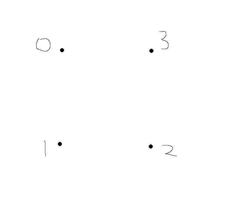
Truly incredible, isn't it? Well, sarcasm aside, it is actually quite incredible that it is that easy to tell the computer where to put those points in 3D space.
Basically all we're doing is saying, hey program, I want these dots here, thanks.
Then they are stored as such.
Step 2, Indices:
In OpenGL, you have your vertex positions, but those alone are not very helpful. We need a way to tell the graphics card how to connect these dots, quite literally. That's where indices come into play. In OpenGL these dots are connected together in what is known as "tris". The term tri, literally means triangle.
When these dots are connected together, your graphics card can fill them in utilizing it's pixel shader cores, but that is beyond the scope of this tutorial. Just know, you need three points to connect the dots, and keep them as triangles. This will allow you to, let's say, put a color to the triangle created between those points. Or maybe you could put a texture there instead. It is up to you. But for simplicity sake, in this tutorial we will be texturing our tris.
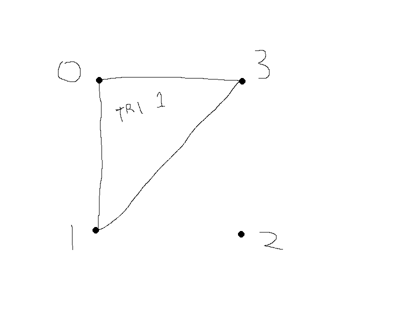
Before we get into texturing, I will show you our two quads that we created at line 43 of meshBuilder.go.
The first image is tri 1, the second is tri 2. Pretty simple isn't it?
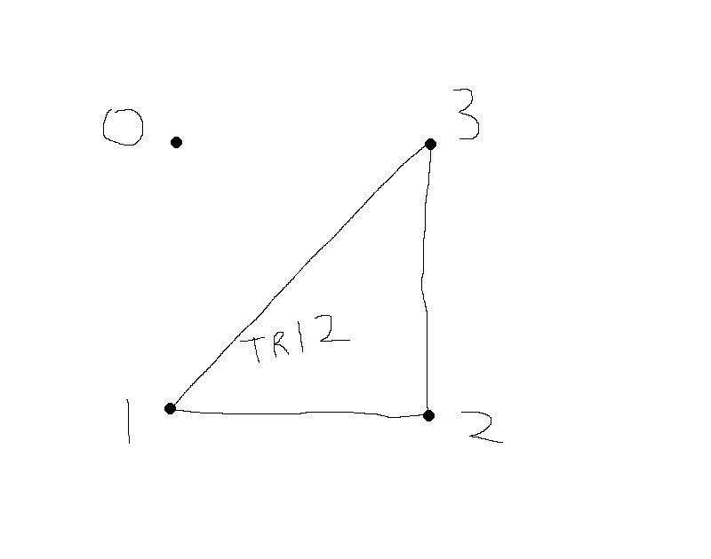
And now we show them together as it's written in the code!

A truly beautiful square. OpenGL has built in magic and knows how to assemble these together, so really, the only thing you have to worry about is making those vertex positions turn into a square using the indices formed into two tris. OpenGL knows what to do automatically. Truly incredible!
Step 3, Winding Order:
Winding order is a very simple concept to grasp. Look at the code for tri 1 which constructs it in the indices and then look at the image for tri 1 above. Now look at the code for tri 2 which constructs it in the indices and then look at the image for tri 2 above. You will notice something very important. They are going counter clockwise. Basically you are telling OpenGL which direction is the face of your tri when you are creating the mesh. Pretty simple, right? This is used for backface culling. We will touch on that in a bit.
I'm going to show you what I mean using the actual program.
As you can see, the face is now rendering outwards where it should be. All is good!
But what happens when we turn this mesh around?
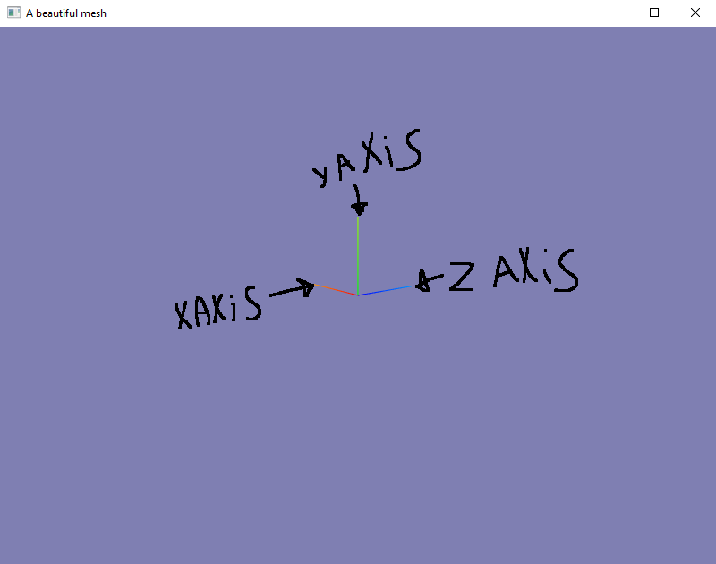
As you can see, backface culling has kicked in. The GPU is basically stopping itself from rendering things it doesn't need to exactly as we told it to.
Why is this important? Well basically if OpenGL had no backface culling, no matter if it had to render a tri or not, it would. This would quickly overwhelm the GPU in complex scenes with millions of tris. This is why Khronos Group had implemented it into OpenGL in the first place. If the GPU detects that it does not have to render the tri, it will automatically be discarded. You can read more about it on Khronos's OpenGL wiki by clicking this link.
If you want to see a very simple example of how to change the face direction of your tri when backface culling is enabled (it's enabled by default in G3N's default shader), here is a very simple thing you can do:
A small interactive example:
On line 45 of meshBuilder.go you can invert the Vertex Position winding of tri 1 in order to make it go clockwise. This will invert the face direction when it is transmitted to OpenGL. A hint: the new order is 3,1,0. You can simply change it to that and now only have of the square will render from the front. Here is an image of that happening:
Front:
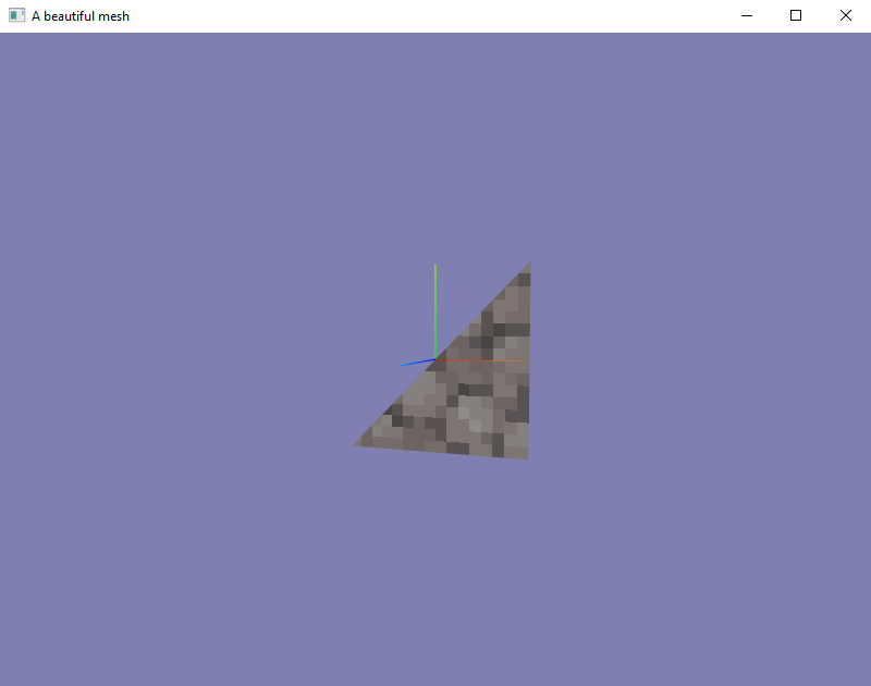
Back:
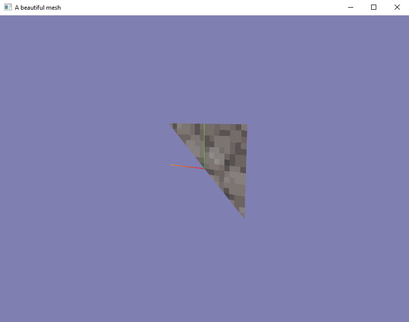
As you see, this can be extremely powerful. But in very complex models, this can overwhelm you. Try to take your time and learn it bit by bit when creating your mesh from scratch.
Step 4, Normals:
Question: I thought all of this code was normal?
Answer: Well, normals are simply the term used to define the front of a mesh used in lighting.
Pretty much, the only thing that you need to know about normals are: they should be pointing outwards if you are going to use hardware lighting with materials. This tutorial only brushes the minimum requried information to utilize G3N's hardware lighting. If you would add this code into line 76 of main.go:
You're going to have to add this to your imports in main.go:
"github.com/g3n/engine/light"
"github.com/g3n/engine/math32"

The code which is added to line 76:

scene.Add(light.NewAmbient(&math32.Color{1.0, 1.0, 1.0}, 1.0))
pointLight := light.NewPoint(&math32.Color{1, 1, 1}, 5.0)
pointLight.SetPosition(0, 0, 3)
scene.Add(pointLight)
When you move the mesh around with the orbital controls, you will see the point light reflecting off of the surface, acting as if it were smooth as glass. This is because this material is by default acting if it were a completely smooth, moderately reflective glass surface. You can customize it, but that's getting too in depth in simply showing you how to make a mesh in G3N.
Here is an image of that. You can faintly see it reflecting. It is actually a lot easier to see when you physically move it around when it's running.
This is why normals are very important. They can quickly get extremely complex. If you were working with a model in blender, you really wouldn't have to worry about this because blender calculates normals for you.
Step 5, UVs:
Now I know what you're thinking, UV as in UV light. But UV are actually the texture mapping. UV is a coordinate system like XYZ. In OpenGL when you hear the term UV, just think "texture map". This is a very simple way to sum that up, but you can read about it here if you want to know more. I'm just going to use texture mapping from here on out, just know that I am referring to UVs.
Texture mapping is one of the most essential parts of meshes. They allow you to do complex model wrapping to make your model look more detailed than it is. You can do some truly crazy things with texture mapping. But for our tutorial scenario, we have made a square that has a texture on it. You can see this being applied to the geometry on line 73 of meshBuilder.go.
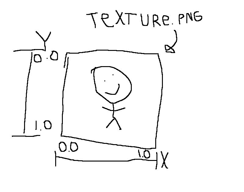
Something very important I would like to get out of the way first. The texture coordinate system on the Y axis (up and down) of the texure map is inverted. Left is 0, right is 1, up is 0, down is 1. Very simple, but this could get extremely confusing if you ever forget this. Hopefully this example helps explain what I mean.
You want your texture definition to start at Vertex Position 0 and end at 3. Basically make it so that it goes to the Vertex Positions in order, 0,1,2,3. You can see this on the line 73 link above. It goes from 0, to 3. If you mess up your UV mapping, you can keep brute forcing it if you really want to, it just becomes a pain in more complex programs to do this.
If your image is not mapped the way you want it to be, you can do a UV shift. This is simply done by taking the bottom coordinate and moving it to the top. This will either move the orientation 90 degrees clockwise or counter clockwise. On line 16, you can turn on the debugDirection boolean to change the texture to a simple "up" texture. Then, on line 70, you can change the uvShift boolean to true to make it turn 90 degrees counter clockwise. I recommend changing debugDirection and doing a rebuild/run, then changing uvShift so you can see it in action.
Step 6, Finalizing the mesh geometry:
So we have gotten all of our data out of the way, we have told the program what our square it is, where to draw it, how it should be facing, and how to map textures to it. What now?
Well, we actually now have to get G3N to tell OpenGL what changes we made.
On line 89 through 98, we are doing this. I am going to lightly touch on this because if I go in depth, I will basically be writing a book.
First we are utilizing mygeometry.SetIndices to transfer the indice data into it. The indice data is set in the OpenGL buffer.
Line 92 to line 98 is basically telling OpenGL our data and data attributes that we made, using G3N's custom C code (gls) which talks directly to it through CGo in unsafe mode. Basically, if you copy that and then use that for your geometry you do not have to worry what that's doing because any further information will confuse you pointlessly. Basically G3N was written so you don't have to worry about and get frustrated by it.
This is also why this is licensed as MIT. You can copy this code and turn it into an operating system desktop environment if you really want to, it's up to you. I'm not holding you back.
Step 7, Materials:
What is a material? Well, it's basically how a mesh looks. How shiny it is, it's refractiveness, how it disperses light, but most importantly, what texture it has. If you want to read more about materials in OpenGL you can click this link. The only thing we're going to worry about in this tutorial is the texture.
On line 105, we create our material out of the standard material structure using white as the base color pallet. This creates an object we can utilize to UV wrap our mesh.
$ var myTexture *texture.Texture2D
This is creating a base blank texture2D that we can "package" into our material. We have also created an error variable on line 112, but that is not so important right now. This basically just tells you if there was an issue finding or loading the texture. On line 115 you can see we are utilizing NewTexture2DFromImage. Basically this is taking in the raw data of the .png image and transcoding it into raw data which OpenGL can understand.
On line 127, we are setting a custom filter. SetMagFilter() allows you to apply custom filters to textures individually to achieve the look you are going for in your game. Since this is a low poly image stretched to fill the entire mesh, we are using gls.NEAREST so it does not attempt to blend (think N64 graphics) the textures together. In higher quality textures, you might want to experiment with gls texture filters to get higher fidelity looks of your meshes.
Finally, on line 130, we plop that texture into the material. Now this material has a usable texture we can apply to the mesh in the next step.
On line 135, we have finally created our mesh! The reason that this does not need explicit (var blah TYPE) or implicit (:= walrus operator) is because on line 18 we explicitly created it to make it modularly accessable throughout the program using the "getter" on line 144. This is only for example though, and you can create these however you see fit.
Step 8, Finally adding to scene:
We finally got here! It's that time! We can now add this created mesh to the scene! But wait, where did that scene variable come from??
Well, if you look at the function initialization on line 20 you can see I'm explicitly requiring a *core.Node pointer in this function. This basically is directly calling on the scene pointer to add our mesh into it. Pretty simple right?
That's basically it. You did it! If you followed along and you understand what's going on you should be proud! Now get out there and make something awesome!
 Documentation
Documentation

There is no documentation for this package.